Engineering-Diy

  • Subscribe to our RSS feed.
  • Twitter
  • StumbleUpon
  • Reddit
  • Facebook
  • Digg
Showing posts with label linux. Show all posts

Sunday, 10 November 2013

Control XBMC from the Raspberry PI GPIO's

Posted on 09:07 by Unknown
I have recently worked on adding external controls for my Raspberry PI CarPC project because while driving it is better to have some physical controls to rely on, rather than looking at the touch screen to find the buttons.
This post provide information on how to set up buttons or rotary encoders to control XBMC from Raspberry PI.

Rotary encoder
Rotary encoders are very cheap and very nice controls(eBay link). You can find them in car stereos for volume control. You can also use them to browse through menu items or to skip to next song etc.
They are looking very similar to a potentiometer, but there are major differences: they can be turned in both directions with infinite steps(you know just the direction of the spin), they provide digital output, a full rotation have a number of steps and they have push button also.
Connections for Raspberry PI should be done as follows:
    + pin to 3.3V
    GND pin to Raspberry PI GND
    SW to one GPIO
    CLK and DT to two GPIOs
When the push button is pressed the pin labelled SW is connected to GND. This can be set up as any push button(see below).

Push button
A push button can have two states on or off. There are two ways to hook up a button to a logical circuit(e.g Raspberry PI GPIO's):
We have to use the first setup(with pull up resistor) for the tool to work properly. So, for the push button of the rotary encoder above, we have to cable it like this:
 
The tool
I have created a tool to allow you interface rotary encoders(and also push buttons) with Raspberry PI GPIO's. Also you can set an XBMC command to be executed for click, left rotation and right rotation.
The tool can be otbained from my Google Code project(link to page).
It is very easy to use it. You just have to accomplish two steps:
    - copy rpi-xbmc-remote in a place where it can be accessed from anywhere(e.g. /usr/bin)
    - call it using sudo rpi-xbmc-remote /path/to/configuration/file

The configuration file
Example:

ip:localhost

button:7:KB:return

encoder:clk:23:KB:up:dt:24:KB:down
The configuration file can reside anywhere on the disk. It provides a way to define two kind of inputs for XBMC: regular button and rotary encoder. Lines should be less than 100 characters in length. Lines starting with # are comments and are not being processed.
 

Example of regular button definition: 
button:7:KB:return
    - 'button' means it is a regular button
    - '7' means use GPIO7 for this button
    - 'KB' means XBMC device map
        "KB" - Standard keyboard map
        "XG" - Xbox Gamepad
        "R1" - Xbox Remote
        "R2" - Xbox Universal Remote
        "LI:devicename" - valid LIRC device map where 'devicename' is the actual
name of the LIRC device
    - 'return' means XBMC button name to be called(see XBMC keymaps)

Example of rotary encoder definition:

encoder:clk:23:KB:up:dt:24:KB:down
    - 'encoder' means it is a rotary encoder
    - '23' means use GPIO23 for rotary encoder CLK
    - 'KB' means XBMC device map for rotary encoder left turn(same as above)
    - 'up' means XBMC button name to be sent for left turn of the rotary encoder
    - '24' means use GPIO24 for rotary encoder DT
    - 'KB' means XBMC device map for rotary encoder right turn(same as above)
    - 'return' means XBMC button name to be called(see XBMC keymaps)

Keep in mind!
You have to put a pull up resistor for every push button you define in the configuration file. If you don't do this then the state of the button will be variable when not pressed(it will oscillate between 0 and 1) and it will behave like it is pressed randomly.


Have fun!
Read More
Posted in controller, debian wheezy, embedded, gpio, linux, push button, raspberry pi, xbmc | No comments

Sunday, 6 October 2013

Keep your linux clock synchronized with gps time

Posted on 03:39 by Unknown
A big problem for a CarPC is that you need a real time clock to synchronize your system with.
For my CarPC, I don't have any RTC module on Raspberry PI, but I do have a gps always connected, which provide accurate date and UTC time.
I have found some tutorials on how I can set up ntp to update the system clock based on gpsd but they didn't worked with any of my gps devices:
ST22 SkyTraq GPS receiver
Columbus V-800
I have followed some links with no luck. I got:
"gpsd:WARN: can't use GGA time until after ZDA or RMC has supplied a year."
or
"gps data is no good"
or
"unrecognized ... sentence"

I have decided to make my own time synchronization based on parsing raw gps data.
You can download an archive containing the scripts from here.

How does it work?
First connect your gps module:
gpsd /dev/ttyAMA0
Then, to get the raw data I used:
gpspipe -R -n10
This command will get the first 10 lines from gps raw data. I got this:
pi@raspberrypi ~ $ gpspipe -R -n10
{"class":"VERSION","release":"3.6","rev":"3.6","proto_major":3,"proto_minor":7}
{"class":"DEVICES","devices":[{"class":"DEVICE","path":"/dev/ttyAMA0","activated":"2013-10-06T09:42:18.793Z","flags":1,"driver":"Generic NMEA","native":0,"bps":9600,"parity":"N","stopbits":1,"cycle":1.00}]}
{"class":"WATCH","enable":true,"json":false,"nmea":false,"raw":2,"scaled":false,"timing":false}
$GPGGA,094220.784,4425.1141,N,02602.8254,E,1,05,1.6,96.1,M,37.0,M,,0000*6D
$GPGSA,A,3,25,05,29,31,21,,,,,,,,3.1,1.6,2.7*3A
$GPGSV,3,1,09,29,61,061,29,21,58,214,37,25,41,146,38,31,33,245,35*72
$GPGSV,3,2,09,05,25,056,30,16,14,314,,18,09,170,19,12,04,138,20*76
$GPGSV,3,3,09,06,02,278,*49
$GPRMC,094220.784,A,4425.1141,N,02602.8254,E,000.0,191.5,061013,,,A*6E
$GPVTG,191.5,T,,M,000.0,N,000.0,K,A*01
The Shell part.
To set UTC time for our unix system we have to issue a command like this:
date -u -s "2013/10/05 12:48:00"
From the raw gps output, we see that GPRMC gives all the needed information about the date and time(see here what the fields mean).
My idea was to capture just GPRMC data from this output and send it as a parameter to a C program which will parse the string and create a new string as needed to set time.
To get the GPRMC string from the raw gps output I have did the following bash command:
gpspipe -R -n10 | sed -n "/GPRMC/,/*/p"
Decomposition of the command:
gpspipe -R -n10 - this outputs the first 10 lines from the gps raw output.
sed -n "/GPRMC/,/*/p" - extracts the line starting with the string GPRMC
I have used unix pipes(| character) to pass the output from gpspipe -R -n10 to the sed command.
The output from this command will be like this:
pi@raspberrypi ~ $ gpspipe -R -n10 | sed -n "/GPRMC/,/*/p"
$GPRMC,100201.786,A,4425.1179,N,02602.8192,E,000.0,191.5,061013,,,A*61
$GPVTG,191.5,T,,M,000.0,N,000.0,K,A*01
 Now, to pass this as program arguments(assuming the program's name is set_date) we have to do the following:
./set_date 21 $(gpspipe -R -n10 | sed -n "/GPRMC/,/*/p")
The C program part.
In this example, argc will be 4 and argv will be as follows:
argv[0] - "./set_date"
argv[1] - "21"
argv[2] - "$GPRMC,100201.786,A,4425.1179,N,02602.8192,E,000.0,191.5,061013,,,A*61"
argv[3] - "$GPVTG,191.5,T,,M,000.0,N,000.0,K,A*01"

The GPRMC output gives 100201 for time and 061013 for date. This means:
UTC time is 10:02:01 and date is 06 October 2013. GPRMC does not provide the full year, so we have to provide the century as an argument to the C program to compute the correct date.

We are only interested in argv[1] and argv[2], so, in the C program we will convert argv[1] to int using atoi(argv[1]) and we will have the century and after this we have to parse argv[2] using sscanf to get the two numbers for time: 100201 and for date 061013. Let's assume we got these numbers in two uint32_t variables:
rawDate = 61013
rawTime = 100201
To get useful data from here we have to do this:
hour = timeRaw / 10000;
minute = (timeRaw % 10000) / 100;
second = (timeRaw % 10000) % 100;

century = atoi(argv[1]);
day = dateRaw / 10000;
month = (dateRaw % 10000) / 100;
year = (century - 1) * 100 + (dateRaw % 10000) % 100;
After this, to create the command we can use sprintf to put everything in an outputBuffer and then call system(outputBuffer) to execute the command.

Read More
Posted in date, GPS, linux, synchronization | No comments

Saturday, 31 August 2013

OpenElec with support for eGalax touch screen

Posted on 09:15 by Unknown
Hi!

Lately I have tested OpenElec for Raspberry PI and found out that it is very very fast, very very small and also it has some great addons(wifi, bluetooth and more).
Speed/size features on an 512MB RaspberryPI:
  - a complete boot is less than 25 seconds
  - cpu is around 30% load
  - memory used is 32%
  - total system size is less than 300MB

Edit. You can download my build from here(contains eGalax module and XBMC patches).
Username is root and password is openelec. The touch screen calibration file should be put in /storage/touchscreen_axes_calib.

Next, I will guide you through the instructions for building(cross compile) latest OpenElec  for Raspberry PI with touch screen support.
For this tutorial let's assume that you have a Linux machine where you will work.

1. Get the latest OpenElec.
git clone git://github.com/OpenELEC/OpenELEC.tv.git

2. Add kernel touch screen module support.
Open the file OpenELEC.tv/projects/RPI/linux/linux.arm.conf and search for "CONFIG_INPUT_TOUCHSCREEN". Replace the whole text line with the following lines:
CONFIG_INPUT_TOUCHSCREEN=y
CONFIG_TOUCHSCREEN_USB_COMPOSITE=m
CONFIG_TOUCHSCREEN_USB_EGALAX=y
CONFIG_TOUCHSCREEN_USB_PANJIT=y
CONFIG_TOUCHSCREEN_USB_3M=y
CONFIG_TOUCHSCREEN_USB_ITM=y
CONFIG_TOUCHSCREEN_USB_ETURBO=y
CONFIG_TOUCHSCREEN_USB_GUNZE=y
CONFIG_TOUCHSCREEN_USB_DMC_TSC10=y
CONFIG_TOUCHSCREEN_USB_IRTOUCH=y
CONFIG_TOUCHSCREEN_USB_IDEALTEK=y
CONFIG_TOUCHSCREEN_USB_GENERAL_TOUCH=y
CONFIG_TOUCHSCREEN_USB_GOTOP=y
CONFIG_TOUCHSCREEN_USB_JASTEC=y
CONFIG_TOUCHSCREEN_USB_ELO=y
CONFIG_TOUCHSCREEN_USB_E2I=y
CONFIG_TOUCHSCREEN_USB_ZYTRONIC=y
CONFIG_TOUCHSCREEN_USB_ETT_TC45USB=y
CONFIG_TOUCHSCREEN_USB_NEXIO=y
CONFIG_TOUCHSCREEN_USB_EASYTOUCH=y

3. Fix ppl version in OpenElec.
Open the file OpenELEC.tv/packages/toolchain/math/ppl/meta and change PKG_VERSION from "1.1pre9" to "1.1pre10"

4. Put touch screen calibration file into the system.
Navigate to folder OpenELEC.tv/projects/RPI/ and create the file usr/share/eGalaxCalibration/touchscreen_axes_calib. This file should have the following contents:
calib_x_d=-21;calib_x_fact=0.658097686;calib_y_d=-50;calib_y_fact=0.408626561;swap_axes=0;click_confines=8
To set up these values please visit this post(at section 4).

5. Put XBMC 12.2 patch.
Get my latest patch from here, rename it to xbmc-300-eGalaxPatch.patch and put it in the folder OpenELEC.tv/packages/mediacenter/xbmc/patches/12.2-18397e1

6. Build OpenElec.
Navigate to OpenElec folder and type:
PROJECT=RPi ARCH=arm make -j3
-j3 option is to use parallel build(if you have more than one cpu's set this number as nb_cpus+1). This option will speed up the build process.
The build process will take couple of hours, but you have o come back once(in the first 10 minutes) and press ENTER for the kernel touch screen modifications to be approved.

7. Install or Update your OpenElec card.
Go to OpenElec build instructions page for RPI and follow the "Install instructions" chapter.

Have fun!
Read More
Posted in calibration, car pc, compile xbmc, eGalax, linux, openElec, raspberry pi, touch screen, touchscreen, tutorial | No comments

Tuesday, 6 August 2013

Car PC project(August 2013 update)

Posted on 12:51 by Unknown
This is an update for my CarPC project.
You can download the latest image from here (username:'pi', password:'a')
The main features are:
Hardware:
  • Raspberry PI model B(256MB ram): ~35$
  • 7 inch display with touchscreen for car rear view camera, from eBay(touchscreen is connected to one USB port): 80$
  • HDMI male to HDMI male cable(golden plated):20$
  • 8GB SDHC class 6 card: 20$
  • 12V(500mA) AC to DC adapter for powering the display
  • 5V(1A) microUSB AC to DC converter for powering the PI
  • ST22 SkyTraq GPS Receiver Module: 25$
  • Reverse Camera: 15$
Software:
[Operating System]
    - Raspbian Wheezy 9.February.2013
    - Custom kernel 3.6.11
        - eGalax touch screen module
        - si470x usb radio module
        - snd-usb-audio module

[Media Center]
    - omxplayer
    - XBMC 12.2 Frodo
        - media formats supported:  listed here
        - sources with objects build on 27.July.2013
        - skin: CarPC-touch(download current version)
            - system shutdown button(safely stop xbmc and safely halt)
            - reload skin button
            - switch to camera view button
        - modified spectrum analyzer(OpenGL with no rotation)
        - eGalax touch screen calibrated
        - eGalax touch screen click&drag fix
        - black rectangle behind XBMC removed
        - patch to add getMousePosition feature to xbmcgui module(used to redirect clicks from the Navigation skin page to X11 using xdotool)

[Navigation]
    - Navit build from source
    - Zoom In, Zoom Out buttons
    - Click sent from XBMC to X11 (Navit Window)

GPS Setup
1. Connect GPS module to UART TX, UART RX, GND and 3.3V or on a usb port.
2. If you are using an UART GPS module, as I did, use this tutorial or any other to setup UART communication.
3. Connect GPS to gpsd:
sudo apt-get install gpsd
gpsd /dev/ttyAMA0

Adding maps to Navit
In order to add new maps to Navit, there is a simple process. First, go to Navit Planet Extractor and download your desired area file(this will be a .bin file).
After this, transfer the file to your Raspberry PI in the folder /home/pi/navit_export/build/navit/maps/. Here, you should also update the existing .xml file and add another entry for your new map. My .xml file is looking like this:
<map type="binfile" data="$NAVIT_SHAREDIR/maps/osm_bbox_11.3,47.9,11.7,48.2.bin" />
<map type="binfile" data="$NAVIT_SHAREDIR/maps/osm_bbox_20.3,43.5,29.9,48.4.bin" />
You can rename your .bin files for easier management

Car Modding
I had to relocate my original Radio/CD player in the trunk and keep it set on aux input source. This included buying about 60m of wires and also harness:
1. Metra 71-9003 Bmw Mini Factory Radio OEM Wire Harness
2. Scosche VW03B 2002+ Vw Audi BMW Radio Stereo Harness

 front without OEM Radio/CD player
trunk with relocated OEM Radio/CD player
Mounted Raspberry PI in the armrest
Safety:
    - The wires are 2mm in diameter with good insulation, resistant at temperature variations
    - I have added fuses(1.5A for the radio, 1A for Raspberry PI, 1A for display, 0.1A for reverse camera trigger, 0.1A for reverse camera video signal)

Bugs:
     - sound pops(will soon disappear by using this hdmi to hdmi and audio splitter)
    - Navigation is behind Video Player -> Navigation isn't visible while playing videos(this isn't a big issue)
Read More
Posted in 7 inch, car pc, debian wheezy, display, eGalax, GPS, kernel rebuild, linux, navigation, Navit, Openstreetmap, raspberry pi, raspbian, resistive, touch screen, touchscreen, wheezy, xbmc 12.2, xbmc frodo | No comments

Friday, 12 July 2013

CarPC first build

Posted on 12:43 by Unknown
Hi!

After working a lot at my CarPC project I have decided to take a break and post about it.

A short preview is here:

You can download my 4GB image from here
If you want to build it by yourself please follow my previous tutorials but replace the three patches with the single patch from here, which is for XBMC12.2. Also read my previous post to find how to calibrate the screen axes.

Features:
  • auto start XBMC
  • eGalax touch screen support with configurable greater area for touch event(8 pixels)
  • improved skin with larger buttons and smooth transitions(link for the skin)
  • System Power OFF button
  • usbmount enabled(so usb MSD's are plug and play)
The new calibration file contains one more entry: click_confines which defines the area for XBMC to distinguish between click and drag actions(touch moves less than 8 pixels before release than action is click, else the action is drag).

Have fun!
Andrei
Read More
Posted in 7 inch, calibration, car pc, debian wheezy, display, eGalax, linux, raspberry pi, raspbian, resistive, touch screen, xbmc 12.2 | No comments

Tuesday, 26 February 2013

Raspberry PI, Raspbian, XBMC and eGalax 7 inch touchscreen

Posted on 00:04 by Unknown
Hello!

I have spent some time lately trying to find a solution to get my 7 inch eGalax touchscreen to work with  Raspbian(Debian Wheezy) in XBMC 12 Frodo and finally got it working as I wanted.

My Setup
  • Raspberry PI model B: ~30$
  • 7 inch display with touchscreen for car rear view camera, from eBay(touchscreen is connected to one USB port): 80$
  • HDMI male to HDMI male connector(from eBay): <2$
  • 4GB SDHC class 4 card
  • 12V(500mA) AC to DC adapter for powering the display
  • 5V(1A) microUSB AC to DC converter for powering the PI
  • USB keyboard


Edit:  I have uploaded my image with XBMC 12 build with eGalax touchscreen support(download it from here, with md5sum c59330154143d9e5e43217322bbd92ce). It seems that you need to request permission and I will give you access. The account is pi and password: a.

Here is what you need to do in order to have a system with Raspberry PI, Raspbian OS and XBMC 12 Frodo stable with eGalax touchscreen working correctly(which means axes calibrated and click working with just one tap&release action):


1. Get latest Raspbian image from here and flash it to an SD card.

2. Build your own kernel with eGalax touchscreen support, like in this post(you will only need to replace kernel.img file and /lib/modules and /lib/firmware folders on the SD card).

3. Build XBMC 12 on Raspberry PI using this tutorial.
Note: After downloading XBMC archive, get this archive and unpack it anywhere.
Apply patches to xbmc files:
cd <patches_folder>
patch -p1 <path_to_xbmc>/xbmc/input/linux/LinuxInputDevices.cpp < LinuxInputDevices_cpp.patch
patch -p1 <path_to_xbmc>/xbmc/input/MouseStat.cpp < MouseStat_cpp.patch
patch -p1 <path_to_xbmc>/xbmc/input/MouseStat.h < MouseStat_h.patch
4. Touchscreen calibration.
Copy the eGalaxCalibration folder from the archive(downloaded above) to /usr/share/ on Raspberry PI. Here, you should have the file touchscreen_axes_calib. It contains four values for the axes calibration and one value for swapping axes.
The simplest way to swap axes is to switch the four wires cable plug's orientation which comes from the touchscreen to the touch controller.

Here is how the calibration was done.

the original behavior(no calibration)

In the picture above, we see that "touch panel values frame" differs from "touch panel physical size frame". When we are pressing the touch we are moving in the "touch panel physical size frame" but when the touch screen is not calibrated the arrow from XBMC is in another place.
  • "touch panel physical size frame" is the screen starting from (0,0) on the left top corner and going to (width, height) in the right bottom corner.
  • "touch panel values frame" is the frame which contains all the number the touch controller is giving.
We see that these frames differs a lot. Our main scope is to overlap the "touch panel values frame" to the "touch panel physical size frame".

In order to do this we need to do three steps(the third one is done in software):
a. Scale the value read from the touch driver x and y) in order to fit 0->width range and respectively 0->height range of the "touch panel physical size frame" the scale value for x axis is:
                       "touch panel physical size frame" width
calib_x_fact = -------------------------------------------------
                            "touch panel values frame" width


                       "touch panel physical size frame" height
calib_y_fact = -------------------------------------------------
                            "touch panel values frame" height

"touch panel values frame" width and height are coming from your XBMC resolution(I have width=1280 and height=720).
"touch panel physical size frame" width and height are a little more trickier to find but nothing hard. In step 2 above, you have calibrated the touchscreen in XFCE. You got some values returned by xinput_calibrator, something like:
Section "InputClass"
    Identifier   "calibration"
    MatchProduct    "eGalax Inc. USB TouchController"
    Option    "Calibration"    "1977 32 1893 131"
EndSection
In my case,
"touch panel physical size frame" width is 1977 - 32 = 1945
"touch panel physical size frame" height is 1893 - 131 = 1762
Now, compute the values and put them in /usr/share/eGalaxCalibration/touchscreen_axes_calib file

b. Translate the "touch panel values frame" to the left and up, to match "touch panel physical size frame".
I didn't find a logical method to do this, because we don't know exactly "where is" the "touch panel values frame", so, in order to find calib_x_d and calib_y_d you have to first set them both to zero and then start XBMC. Now, put some sharp pointer on the screen and observe the distances between the cursor on the screen and your pointer's position. Try to approximate these x and y deviations(measured in pixels) and put them in the /usr/share/eGalaxCalibration/touchscreen_axes_calib file.

c. Revert direction of axes. This is done in the software(from patches).

5. Math behind.
To accomplish these transformations the following formula was implemented in the file
xbmc/input/linux/LinuxInputDevices.cpp
pointer.x = screen_width - value_read.x * calib_x_fact - calib_x_d;
pointer.y = screen_height - value_read.y * calib_y_fact - calib_y_d;

After I have successfully calibrated the touchscreen I have discovered that single click was not possible from the touchscreen, just double click. After digging through the code, I have found that this was caused by drag action which was triggered because the previous values of the touch were far(more than 5 pixels) from a new press. For example, at the start of the program, cursor is set at 0,0 coordinates; if user is trying to press a button, let's say at 100, 300, the program(XBMC) will calculate the distance between these two points and will find out that this is greater than 5.
Pythagorean theory:
(100-0)x(100-0) + (300 - 0)x(300-0) is greater than 5x5 XBMC will treat this as a drag event.
This drag issue is not caused when you double click, because the previous point in the second click action is very close to the second click point. This also works for mouses, because the previous value of the pointer is always very close to the new value of the pointer(because mouse's pointer drags on the screen and it doesn't jump - so each new value is very close to the previous one).

I have developed an algorithm to avoid this issue:
When the user is pressing the screen(x,y), the touch values are being set to (screen_width+1, screen_height+1 -> outside of the visible screen) just at the first event read(which is BTN_TOUCH PRESS).
After this event, the program will receive multiple X and Y absolute values events. The first two events, one for X and one for Y are used to set the previous X value, respectively previous Y value to the current X respective current Y values. And from now on distance is measured and this is preventing no unwanted drag action.
The user's finger/pointer will not stay at a single point, because the touchscreen's lack of precision, so it will move around 5-6 pixels in x and y directions.
I have also set the click distance to 7. You can change this by changing click_confines value in xbmc/input/MouseStat.h. Originally it was set to 5, but this is not very good for touch screens(I had to click with a sharp pointer and with my nail always, but with a value of 7 I can click with my finger with a slight touch -> really nice).

Enjoy!

Read More
Posted in 7 inch, calibration, display, eGalax, kernel rebuild, linux, raspberry pi, raspbian, resistive, touch screen, touchscreen, tutorial, ubuntu, wheezy, xbmc 12 | No comments

Friday, 28 December 2012

STM32F3 Discovery on Windows with Eclipse and OpenOCD

Posted on 15:24 by Unknown
Hi!

Because of a lot of requests, I have decided to make the Windows version of the tutorial for setting up STM32F3-Discovery board, with free tools.

First, download ST-LINK V2 driver from here. Open the archive and install what is in it.
Then plug the device and let the driver install.
Now, get the latest OpenOCD installer from here and extract it somewhere. Copy <openocd_path>\scripts\board\stm32f3discovery.cfg to <openocd_path>\bin folder
Now you should be able to connect to the board in Command Prompt like this:
D:\embedded\openocd-0.7.0-dev-121112115725\bin>openocd-0.7.0-dev-121112115725.ex
e -f stm32f3discovery.cfg
Open On-Chip Debugger 0.7.0-dev-00079-g08ddb19 (2012-11-12-17:14)
Licensed under GNU GPL v2
For bug reports, read
        http://openocd.sourceforge.net/doc/doxygen/bugs.html
adapter speed: 1000 kHz
srst_only separate srst_nogate srst_open_drain
Info : clock speed 1000 kHz
Info : stm32f3x.cpu: hardware has 6 breakpoints, 4 watchpoints
Now close the Command Prompt.

Download latest Eclipse.
Go to Eclipse download page and download Eclipse IDE for C/C++ developers. Extract it and start eclipse.exe. Go to Workbench.

Set up Eclipse.
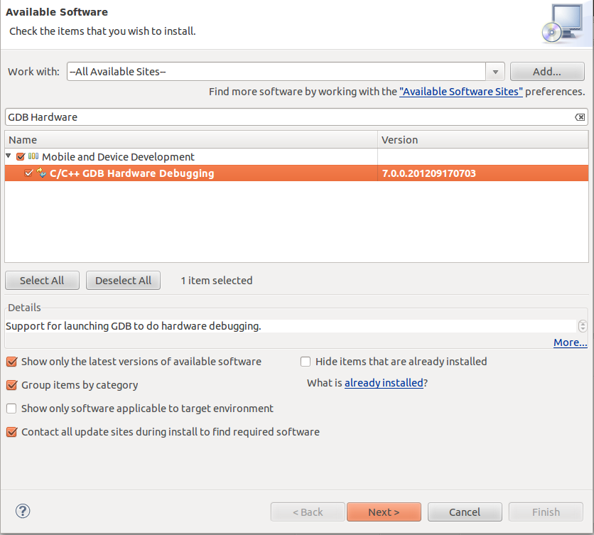
Go to Help->Install New Software, select All Available Sites in Work With dropdown list. Enter "GDB Hardware Debugging" in the search box and install the package. Download Arm Eclipse Plugin from here and then go to Help->Install New Software in Eclipse. Click Add and then click archive and select the previous downloaded file. Then select the packet and install it.

Install GCC Arm Embedded toolchain from here.

Now we need some Linux tools like make and rm for Windows. Download Cygwin from here. Select whichever mirror you want. Search for "make" and select the binary from Devel dropdown. Click next and wait for it to install.
Now, download this project and import it in Eclipse Workspace. Right click project and select  Properties->C/C++ Build->Environment. Here, check if PATH variable has link to toolchain and to Cygwin binaries folders. Here, you can add <gcc-arm-none-eabi-4_6-2012q4/arm-none-eabi/include> path for the Eclipse IDE to find some headers like stdint.h.
If everything  was installed correctly you should be able to clean the project and to build it.

With the project selected, click Run->External Tools->External Tools Configurations and select from the left the configuration named OpenOCD(win). Check if the path for OpenOCD at top is correct.
Now, click Run.

After this, click Run->Debug Configurations and select from the left Navigation-debug. In the Debugger tab check if the arm-none-eabi-gdb.exe path is correct. Now click Debug and you should see the Debug Window from Eclipse and the Program counter pointing at the first instruction from main().

Read More
Posted in cortex m4, discovery, eclipse, embedded, linux, openocd, stm32f3, tutorial, windows | No comments

Wednesday, 28 November 2012

STM32F3-Discovery Usart with printf

Posted on 10:11 by Unknown
Hi,

The next step after setting up the Development Environment for STM32F3-Discovery was to communicate with computer via serial port.
I have added usart support to my board using USART2 module, which had TX connected to PA2 pin and RX to PA3 pin(both with alternate function set to 7).

The next step was to connect the pins to PC serial port. I have used a MAX3232 module(note that you need a chip with 3.3V support).

After using printf function I have noticed that linker asks for some functions like _write which are used internally. I have added a file newlib_subs.c to implement these function.

You can download the example project from here.
The settings for usart communication are:
baudrate: 115200
parity: none
data bits: 8
stop bits: 1
flow control: none

If you want to use interrupts to read from USART you can use the code from here.

You can check my project via svn from my repository using:
svn checkout http://andrei-development.googlecode.com/svn/branches/dev/stm32f3-discovery


Read More
Posted in cortex m4, discovery, eclipse, embedded, linux, openocd, printf, stm32f3, tutorial, ubuntu, usart | No comments

Saturday, 17 November 2012

STM32F3 Discovery + Eclipse + OpenOCD

Posted on 02:47 by Unknown
Hi,

ST launched in September a very interesting development board(STM32F3-Discovery). It is a very cheap one(I have got myself one for ~10$). It has a debugger integrated(STLINK) and also some great sensors:
- ST MEMS LSM303DLHC, which contains 3 axis accelerometer(to measure acceleration intensity on each axis) and 3 axis magnetometer(to measure angles to a fixed point - the Earth's magnetic North)
- ST MEMS L3GD20, which has 3 axis gyrometer(to measure rotation speed)
This board is very good for automated pilot controller projects.

After unpacking the board I have found that it was supported just by commercial software and tools. As I am an opensource kind of guy I have struggled myself some time to get this working with Eclipse, OpenOCD and a free toolchain, on Linux.
I have used Ubuntu, but I think the process is the same on every distribution. Also, with little adjustments it can work on Windows.

Here are some steps, that you have to follow to get the led blinking example to work:
1. Install Java Runtime Environment. Here are some steps for Ubuntu:
sudo add-apt-repository ppa:webupd8team/java
sudo apt-get update
sudo apt-get install oracle-java8-installer

2. Install Eclipse. Get Eclipse IDE from here (grab the Eclipse IDE for C/C++ Developers) and unpack it somewhere

3. Install GDB Hardware Debugging. Open Eclipse go to Help->Install New Software and then search for GDB Hardware Debugging and install it.

   Install GNU ARM Eclipse plugin. Get it from here and install it from Help->Install New Software->Add->Archive and select the downloaded .zip file.

4. Install some dependencies. Paste following text in Terminal:
sudo apt-get install git zlib1g-dev libtool flex bison libgmp3-dev libmpfr-dev libncurses5-dev libmpc-dev autoconf texinfo build-essential libftdi-dev libusb-1.0.0-dev

5. Install OpenOCD(version>0.6.1). Get it from here and unpack it. Then, navigate to the extracted folder and type in Terminal:
./configure --enable-maintainer-mode --enable-stlink 
make 
sudo make install

6. Add rule for Stlink to be accessed without sudo. Type in Terminal:
sudo gedit /etc/udev/rules.d/99-stlink.rules
Paste the following text:
ATTRS{idVendor}=="0483", ATTRS{idProduct}=="3748", MODE="0666"
Type in Terminal:
sudo udevadm control --reload-rules
Now, with the board connected to PC you can enter  in Terminal:
openocd -f /usr/local/share/openocd/scripts/board/stm32f3discovery.cfg
The following text should appear:
Open On-Chip Debugger 0.6.1 (2012-10-29-22:02)
Licensed under GNU GPL v2
For bug reports, read
    http://openocd.sourceforge.net/doc/doxygen/bugs.html
adapter speed: 1000 kHz
srst_only separate srst_nogate srst_open_drain
Info : clock speed 1000 kHz
Info : stm32f3x.cpu: hardware has 6 breakpoints, 4 watchpoints
You can close the Terminal now.

7. Install toolchain.  You can use Codesourcery toolchain, like described in this step, or you can use GCC Arm Embedded toolchain(from here) which has support for hardware floating point unit and which is free and it is easier to install.
For Codesourcery follow the next steps:
Go to Codesourcery and download IA32 GNU/Linux Installer. To install it open the Terminal and navigate to the folder where it is downloaded. Type:
chmod a+x arm-2012.03-56-arm-none-eabi.bin 
./arm-2012.03-56-arm-none-eabi.bin
Then select next at every step. 

8. Download sample project. Go to this page and download stm32f3.tar.gz file and unpack it.

9. Open the project in Eclipse. Open Eclipse and go to Workbench. Click File->Import and then select General->Existing Projects into Workspace. Select the downloaded project and click finish.
This is a makefile project, so you have to edit makefile if you want to change some project settings. The frst thing you should do is open the Makefile file and check at the very beginning if the toolchain path is correct. This should be like:
TC = <path_to_toolchain>/arm-none-eabi
Now you can build. right click on project name and select build. The correct output is in the Console tab from Eclipse(ignore the warnings and errors from Problems tab).

10. Debugging. After the project was builded correctly select Run->External Tools->External Tools Configuration. Select OpenOCD(restart) in the left tab and click run.
Now, right click project and select Debug as->Debug Configuration and then
select in the left stm32f3-debug and then click Debug.
Note: If you want to add more source files you can add them in the src folder. New headers should be added into hdr folder. If you want to add another folder you have to specify it like the LIB_SRCS in the Makefile and also create LIB_OBJS like variable in the Makefile.

Happy free coding and debugging! :-)
Read More
Posted in cortex m4, discovery, eclipse, embedded, linux, openocd, stm32f3, tutorial, ubuntu | No comments
Home
Subscribe to: Posts (Atom)

Popular Posts

  • STM32F3-Discovery Usart with printf
    Hi, The next step after setting up the Development Environment for STM32F3-Discovery was to communicate with computer via serial port. I hav...
  • Keep your linux clock synchronized with gps time
    A big problem for a CarPC is that you need a real time clock to synchronize your system with. For my CarPC, I don't have any RTC module ...
  • STM32F3 Discovery on Windows with Eclipse and OpenOCD
    Hi! Because of a lot of requests, I have decided to make the Windows version of the tutorial for setting up STM32F3-Discovery board, with fr...
  • Control XBMC from the Raspberry PI GPIO's
    I have recently worked on adding external controls for my Raspberry PI CarPC project because while driving it is better to have some physica...
  • Adding 7inch display with touchscreen to Raspberry PI
    Hi! First thing I got in mind when seeing Raspberry PI was "car PC project". The targeted display was 7 inch with touchscreen. I h...
  • Car PC project(August 2013 update)
    This is an update for my CarPC project. You can download the latest image from here (username:'pi', password:'a') The main f...
  • Raspberry PI, Raspbian, XBMC and eGalax 7 inch touchscreen
    Hello! I have spent some time lately trying to find a solution to get my 7 inch eGalax touchscreen to work with  Raspbian(Debian Wheezy) in ...
  • OpenElec with support for eGalax touch screen
    Hi! Lately I have tested OpenElec for Raspberry PI and found out that it is very very fast, very very small and also it has some great addon...
  • Build XBMC Frodo from source in Raspbian on Raspberry PI
    Hi! After struggling couple of days in finding the best way to build XBMC on Raspberry PI I have finally got a working solution(haven't ...
  • STM32F3 Discovery + Eclipse + OpenOCD
    Hi, ST launched in September a very interesting development board( STM32F3-Discovery ). It is a very cheap one(I have got myself one for ~10...

Categories

  • 7 inch
  • calibration
  • car pc
  • compile xbmc
  • controller
  • cortex m4
  • date
  • debian wheezy
  • discovery
  • display
  • eclipse
  • eGalax
  • embedded
  • gpio
  • GPS
  • kernel rebuild
  • linux
  • navigation
  • Navit
  • openElec
  • openocd
  • Openstreetmap
  • printf
  • push button
  • raspberry pi
  • raspbian
  • resistive
  • stm32f3
  • synchronization
  • touch screen
  • touchscreen
  • tutorial
  • ubuntu
  • usart
  • wheezy
  • windows
  • xbmc
  • xbmc 12
  • xbmc 12.2
  • xbmc frodo

Blog Archive

  • ▼  2013 (8)
    • ▼  November (1)
      • Control XBMC from the Raspberry PI GPIO's
    • ►  October (1)
    • ►  August (2)
    • ►  July (1)
    • ►  February (2)
    • ►  January (1)
  • ►  2012 (4)
    • ►  December (1)
    • ►  November (3)
Powered by Blogger.

About Me

Unknown
View my complete profile